Wednesday, 20 November 2013

Week 8, Texturing X-Wing

Once i was comfortable with the different techniques regarding creating and applying material to objects i started with my first model the X-Wing.

Learning form previous exercises i decided that to get the most control and the highest level of detail to do my models justice, that using the unwrap modifier would be the best way forward. I have also learned that as my model is highly complex and i made its mainly one large mesh apart form small details, I would break down the model into smaller easily distinguishable parts. Then when i apply the modifier the polygons will be fewer and much easier to paint on. This will also help me get nice clean lines on different parts of the ship.

The first step was to break the model down as if it has literally been assembled in a physical sense. Again this greatly improves the precision i will be able to get when applying the materials.

I identified the parts of the ship that would have different colors and textures and separated them individually.

For example the roll cage of the cockpit is a different color to the main fuselage and a different material (ie, metal and glass) to the screen, so i detached this from the main mesh.

Detaching cockpit roll cage 

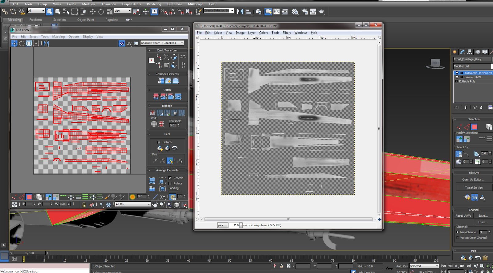
Painting Rollcage map in GIMP


Detached back of Fuselage 


Sometimes even when the materials are the same like on the front of the fuselage or parts of the wings, as it has different colored panels, i decided to remove the panels individually in some cases this gave me cleaner lines and textures on the objects.

Main panels and red side panels being detached individually 


Red wing panels being textured separately


When i had rendered the templates i could take them in to Gimp and start building up paint layers and applying effects to the materials. I used a noise map effect to give the metal textures an authentic brushed metal look, and used different style and sized brushed to create a weathered effect on parts of the fuselage. When you paint these templates in Gimp it gives you a lot of freedom to create individual and realistic looking textures. And because they are all unwrapped using the UVW modifier when you apply them on them model they fit perfectly and look quite realistic. 

Fuselage map and material before application 
     

X-Wing with front of fuselage and cockpit materials applied 

I could also add more effects in the material editor in 3Ds Max to get a more accurate representation of the materials. For example changing the specular and gloss levels on the material to give the metal a shiny and reflective appearance. Also with the glass i changed reduced the opacity slightly and increased the reflection parameter to make the glass look more realistic. If i had time with the models i could of introduced some geometry inside the cockpit and then i could have it so you could see through the glass completely and into the pilots bay.   

Continuing the method of detaching and unwrapping individual parts of the ship, although very time consuming starts to give a realistic looking ship. 

Engines Textured 

Fuselage fully textured 


There are times when the UVW Unwrap modifier has its downfalls though. For small and high poly objects the maps sometimes become highly complicated and impossible to distinguish and work with.

Unwrapped polygons 
  
In this example the polygons are for small wires and details on the ship and due to their size a UVW unwrap is not only overly complicated but unnecessary. I can just apply a basic material to these smaller less conspicuous objects and still get a realistic overall effect by using reflective maps and bump maps.

When the entire ship was textured to my satisfaction i could start to re-attach parts of the ship back together. In some cases i decided not to re-attach and just group objects, as the model was originally mainly one whole mesh, which i now know is not always best practice. Especially when it comes to the animation, when i might want to animate individual parts of the ship like the wings folding out for example.  

Rendered Views of fully textured X-Wing


I am pleased with the final model now its textured, the materials look realistic and reflect accurately the original source images and models i have been working with. The detail i was able to achieve by unwrapping each part of the ship and texturing individually is definitely something i will use again in my other models. Although i might experiment more with the different map channels that are available within the material editor. Overall though the first model was a success. 


Saturday, 16 November 2013

Week 7. Materials and Texturing

When all the  models where finished to a standard i was happy with i had to move onto the making and applying materials to the models.

Before i started trying to texture the models i tried out the various techniques of applying and creating materials that 3ds max has to offer.

The most basic way of applying a material is to just drag it onto the desired object. This gives you no control on how the material is displayed on the object though. While this will work for basic materials that have no pattern or particular detail, if any kind of precision is required we would be better off looking to add a UVW map modifier.

The UVW map modifier allows you to chose how you would like the material to be displayed on the object, for example as a cylinder, sphere or box.


  Planar and Box Mapping using UVW map modifier  


This gives you more control on how you want the material displayed but it still limited. The objects still have to conform with one of the mapping options available, which are still pretty basic. My ships are far more complex and mainly consist of irregular shapes and will require unique maps for each part the model.

To get the most amount of control over the maps and how they are displayed we will use the UVW unwrap modifier. This allows you unwrap the desired polygons in different ways and create a flat or box map of the object. Having all the polygons laid out flat separately allows for a more accurate application of materials. If the selected object is complex it can however become difficult to establish which polygons are which. This can partly be resolved by stitching polygons back together, which 3ds max allows you to do. This helps to reestablish where each polygon is in relation to the entire object. Which is necessary if you are going to create a pattern of some kind or require a seamless material.

Stitching a box back together at the edges 


Flatten map option of Unwrap UVW modifier, with seams identified

If you desire you can also choose which edges will be the seams where the object will unwrap to and get a flat easily distinguishable map.

Along with the flatten map options you can also use box mapping. Box mapping is slightly different as keeps the object in fewer pieces. This option can work better for high poly objects like spheres, when you need to wrap a material or pattern round a smooth surface and have no seams.

Sphere Box map UVW template 

Flatten Map UVW template of same sphere

While not a huge difference w can clearly see that box map is in fewer pieces and makes texturing the template slightly easier.

When we have a UVW map and template we are satisfied with we can take the template into some image manipulation software such as Photoshop or Gimp and paint directly onto it. For future reference i will be using gimp for all my texturing.

3Ds Max has in itself vast resources for materials creation, for this project though i will be using the simplified version of the material editor. We can still produce some interesting  materials and effects though with this compact version.  

Combining different procedural maps we can create a good looking sky and clouds material which can be seen form the ground or above depending on your preference.

Creating a sky clouds material using procedural maps 

Rendered view of completed material 


Thursday, 7 November 2013

Other small side projects

Modelling a head tutorial 


Helmet tutorial 

This tutorial introduced me some interesting techniques like extrude to spline. This allows polygons to follow a path created using a 2d spline. Enabling a much smoother, less problematic and time consuming way of getting the desired outcome.


Friday, 1 November 2013

Lambda Class Imperial Shuttle Model

This is my third and final model for this assessment and with each model things get a little easier. I find setting up the studio is no longer a chore and I'm now comfortable with this aspect of the software.  

Imperial Shuttle Studio

Even though i could only find one clear blueprint that shows only two views of the shuttle i felt confident with the experience i have gained so far that this would suffice. I will not always be able to find 3 or more detailed blueprint images of a model so some intuition and improvisation will inevitably be needed so why not start now.    

Start of Fuselage

When modelling the fuselage i had to add a significant amount of edges and polygons to create the rounded, curved outer part of the fuselage. I know keeping the poly count low and as efficient as possible is a fundamental idea in modelling, however sometimes to get the desired shape you have little choice. I could later remove unused edges to reduce this count slightly. Like at the back and front of the fuselage where the faces are flat and not curved like on the sides. The more edges i have though enabled for a more accurate and gradual curvature of the fuselage.

Fuselage detail

Removing unused and unnecessary polygons at rear of fuselage 

In previous projects i have, as much as i could modify one base shape as much as i could. This did bring its own set if problems though and this time i am using a higher number of separate parts of the model which i can then just group together. This will not only help when i come to texture the model but also makes it easier for me to modify and single out one particular part of the ship without having to adjust anything else. When i had one complex shape with thousands of vertices you can sometimes select more than you want (I am still on a steep learning curve) and that unwanted modifications. Sometimes i wont even be aware of them until later on and then its a real struggle to correct these kind of mistakes. 

Top Fuselage box and wing connector 

Top Wing Started

Top wing advanced

Top Wing Finished


Again when adding details to the wing and fuselage i created new shapes and used the auto grid option for greater accuracy on uneven surfaces.

Top wing detailed and more fuselage detail 

The cockpit is also be a separate object along with the neck of the cockpit that connects it to the main fuselage. This could be thought of as a more realistic approach because aircraft's and vehicles (Fictional as this one might be) are usually made up of individually constructed parts then put together at the end. So even if some parts don't seamlessly blend into one another is not unrealistic and still gives an accurate representation.
 
Early stage cockpit

Beveling and extruding cockpit view port 

Adding detail to cockpit

More cockpit detail

Complete detailed cockpit and cockpit neck

Adding the fuselage guns

Fuselage guns complete

Fuselage air intakes early stage

Air intakes complete

Once all the fuselage detail was complete and correct it could be grouped together for easy access and manipulation.

The lower wings were originally planned to be two separate entities. However as they are a mirror of each other and not the same object in two different places (Like on an X-Wing for example) this was not appropriate. So i decided that making one then attaching it to the main fuselage that has a symmetry modifier i would get two identical but mirrored wings. I can then detach the wings again later when i get to adding materials, keeping with the theme of having many smaller objects as opposed to one large complex one.

Lower wings attached and mirrored 

Detailed lower wings

Adding lower wing gun mounts

Lower wings detailed with guns finished 


When adding the detail to the back of the fuselage i have used less objects than in previous models to try and keep the poly count lower and improve the overall efficiency. I didn't want to go as far as to add no 3D details at all as this would impact the overall quality of the model.


The finished model almost exactly matches my blueprints and I'm very pleased with the accuracy of the shuttle. Its more efficient than previous models too as i was less worried about the actual modelling as i have a small amount of experience now. Which made me relax and think about this aspect of modelling more.

Shuttle in x-ray mode with blueprints visible

Four way view of finished shuttle

More angles of Imperial Shuttle